7. MEP Threshold Hunting
Motor Threshold Hunting function of the BEST Toolbox, trigger the stimulating device on trial by trial basis in a given inter-trial-interval and measures the Amplitude of MEP and then adapt the stimulation intensity for next trial on the basis of current MEP amplitude. It also presents you online results of MEPs and Stimulation Intensity traces in order to visualize the MEP shape and its threshold stability throughout the procedure.
7.1. Parameters Syntax
7.1.1. Brain State
In Brain State Independent case, Inter Trial Interval controls the timing of the stimulus whereas in Brain State dependent case, real-time EEG analysis allows to track the ongoing Phase and Amplitude thresholds thereby allowing to determine specific Brain States such as mu-Rhythm Peak Phase etc. and then delivers the stimulus upon a parametric case match.
7.1.2. Input Device
Select the input device using drop down menu from previously added devices
7.1.3. Inter Trial Interval
ITI scalar, or a range in seconds e.g. 4 or [4 6] or a cell array in order to create ITI based experimental conditions e.g. {4,5,6}
7.1.4. Threshold Method
Select one of the two statistical threshold estimation methods that have been implemented:
Adaptive Staircasing Estimation [1]
Maximum Likelihood Estimation [2] – Dependent on MATLAB Statistics and Machine Learning Toolbox
7.1.5. Trials Per Condition
Various conditions can be created using ITI, Oscillation Target Phase and/or Amplitude and using the interactive Stimulation Parameters Designer. This field applies to all the created conditions and should be a scalar number e.g. 10 or 20 etc.
7.1.6. EMG Display Channels
Type the channel name as a cell array in order to visualize its online results e.g. { ‘APBr’}. Note that the channel name must resolve to the name in your streaming data, however Display Channels does not contributes for Threshold Measurement, these channels are merely for visualization e.g. in case when neighboring muscles are also required to be monitored.
7.1.7. EMG Extraction Period
[min max] in ms
7.1.8. EMG Display Period
[min max] in ms
7.1.9. MEP Search Window
Time window to look for the MEP P2P amplitude. [min max] in ms
7.1.10. Trials to Average
Both of the threshold methods , average certain number of trials in order to estimate the final threshold value, this parameter is specified as a scalar e.g. 10 and can be updated in run time as well.
7.1.11. Real-Time Channels Montage
1xN cell array of Channel Names being streamed from the bio signal processor e.g. { ‘C3’, ‘FC1’, ‘FC5’, ‘CP1’, ‘CP5’}
7.1.12. Real-Time Channels Weights
1xN Numeric array of weights indexed w.r.t. to Channels Montage explained above e.g. 1 -0.25 -0.25 -0.25 -0.25
7.1.13. Frequency Band
Choose the respective frequency band from the dropdown (Hz).
7.1.14. Peak Frequency
Scalar Peak Frequency in Hz. In order to import it from created or successful rsEEG Measurement Protocol, select the respective rsEEG Measurement protocol from the adjacent dropdown menu.
7.1.15. Target Phase
1xN Numeric array of Phase angles in radians. This parameter also creates N experimental conditions crossed over with all the other experimental conditions. If columns in this parameter is balanced with the rows in Amplitude Threshold parameter, then balanced conditions are created otherwise these 2 parameters are also crossed over.
7.1.16. Phase Tolerance
Scalar Tolerance value in radians. Defining absolute target phase angles in order to detect a brain state is often prone to error mainly due to the resolution of data obtained after sampling rate transition. In order to overcome this digitization resolution error another parameter has to be defined such that the vicinities of the target phase shall be made clear to the detection algorithm. For an instance, while detecting a 0 radians phase, the phase vector would probably look like this [-0.001324 -0.00234 0.00243 0.004324], and since none of them are mathematically equivalent to zero therefore in order to not allow to skip such Oscillatory Peak events and to increase the accuracy of the phase detection, a tolerance value is to be provided.
7.1.17. Amplitude Threshold
Nx2 Numeric array of Amplitude Thresholds. The 2 column dimensions are minimum and maximum thresholds where as N (number of rows) creates N Amplitude Threshold conditions crossed over with all the other experimental conditions. If columns in this parameter is balanced with the rows in Target Phase parameter, then balanced conditions are created otherwise these 2 parameters are also crossed over. Units are selected from the drop-down adjacent to the parameter.
7.1.18. Amplitude Assignment Period
If the Amplitude Threshold units are percentile, then the percentile is calculated over a certain time period defined in this parameter. This parameter enables the Brain State detection algorithms to cope with the variations in amplitude of large scale oscillatory activity e.g. due to variations in background neuronal activity.
7.1.19. EEG Extraction Period
[min max] in ms
7.1.20. EEG Display Period
[min max] in ms
7.1.21. EMG Preinervation Search Window
[min max] in ms. Default is [-50 -5] i.e. 50 ms before stimulation to 5 ms before stimulation. The preinveration search window is used to measure amplitude of EMG in this duration to provide checks for quality control and Active Motor Threshold hunting.
7.1.22. EMG Preinervation Amplitude
[amplitude] in uV. Default is [200] i.e. The trials having EMG amplitude of or greater than 200uV during the preinervation search window period are considered bad and rejected and replaced immediately.
For Active motor threshold hunting, this parameter can also be used to provide range of max and min [min max] e.g. [100 300] uV amplitude as user-defined acceptable range of EMG muscle activity e.g. 10-30% Maximum Voluntary Contraction (MVC) action.
7.2. Creating Conditions Using Stimulation Parameters Designer
The Target Channels and Stimulation Trigger pattern can be defined in an interactive Stimulation Parameters Designer comprising of a tabular and graphical view. Following video illustrates that how conditions can be created using the intuitive designer.
7.3. Starting the Protocol
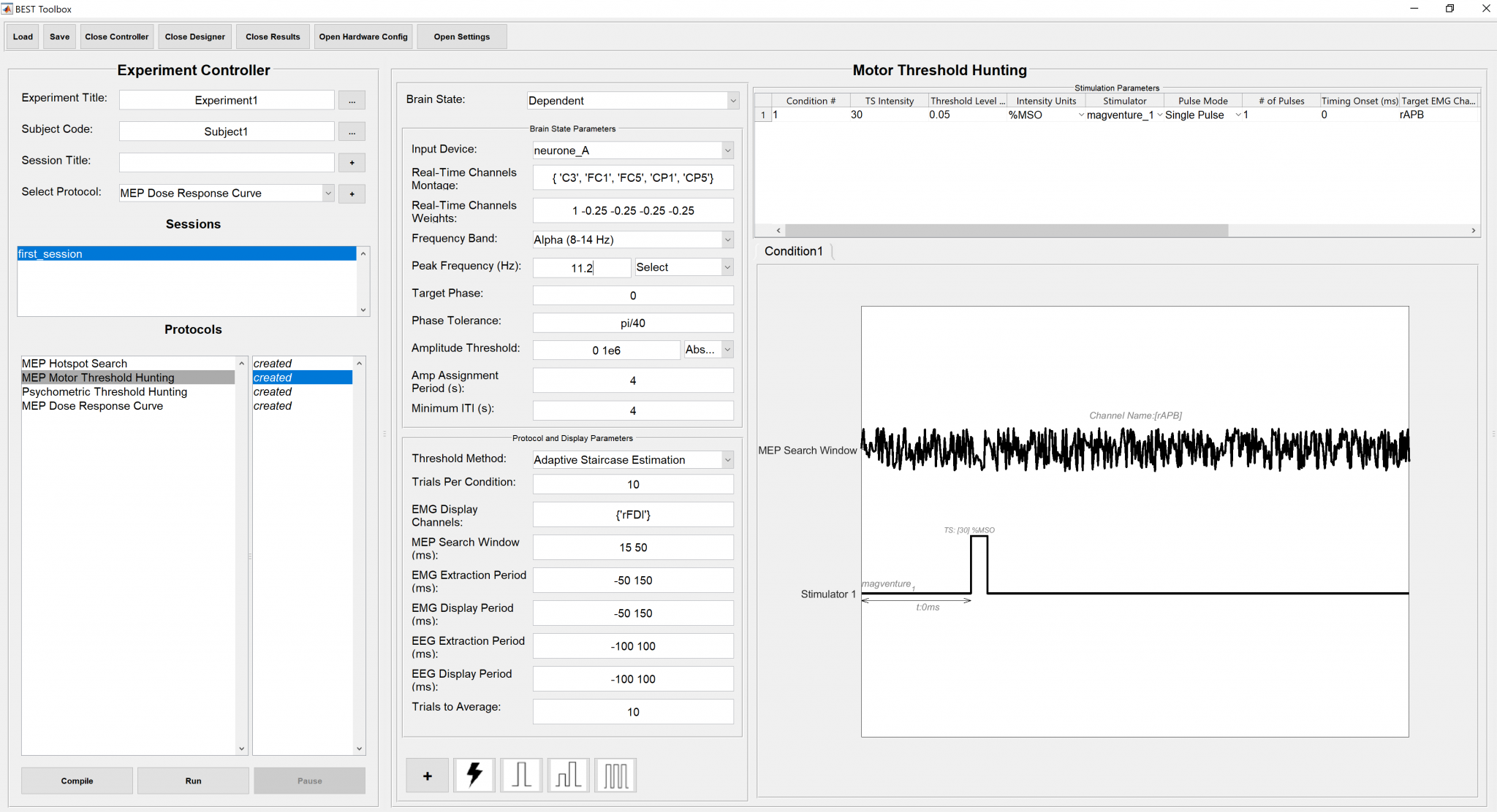
To start Motor Threshold Hunting Protocol, just press the “Run” button at the bottom of the “Experiment Controller”. The measurement can be stopped, paused/unpaused. In order to check if all the parameters have been setup correctly, pressing the “Compile” button would prompt the results of compiled code whether its good to go or not.
An instance of the filled stimulation parameters panel is shown below.
7.4. MEP amplitude estimation procedure
MEP amplitude estimation follows procedure described in Bergmann et al, Journal of Neuroscience 2019.
7.5. References
Taylor, Martin & Creelman, Douglas. (1967). PEST: Efficient Estimates on Probability Functions. The Journal of the Acoustical Society of America. 41. 782-787. 10.1121/1.1910407.
Pentland, A. Maximum likelihood estimation: The best PEST. Perception & Psychophysics 28, 377–379 (1980). https://doi.org/10.3758/BF03204398